Editorial Disclaimer
The views expressed in articles published on FIRES do not necessarily reflect those of IES or represent endorsement by the IES.
By Naomi J Miller, FIES
Pacific Northwest National Laboratory
Any lighting specifier will tell you that in spite of decades of experience, they can be surprised by the amount of glare from a luminaire when they get it installed on a job site. On North American product cuts sheets and photometric summaries, there is nothing that will reliably tell us whether a luminaire will be innocuous in terms of brightness for the viewer, or outrageously painful. This is true whether the luminaire is being installed indoors in an office, or outside on a pedestrian walkway.
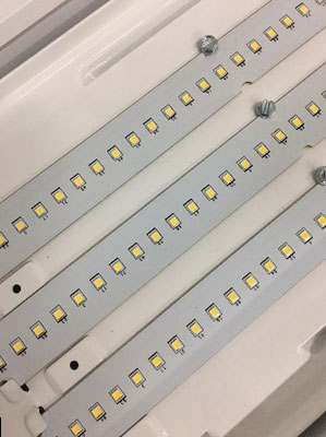
This issue seems to have grown worse since LEDs have usurped the lighting market. Too many luminaires are offered with arrays of bare LEDs, illustrated on cut sheets with daytime product photos of unilluminated luminaires.
Why? We are all grownups here. We have math and equations and computers and human factors researchers and vision scientists and photometric wizards and optical designers and smart people galore. Why can’t we figure this out?
Some or all of the six factors listed below have been incorporated into glare metrics such as veiling luminance ratio and glare control mark for roadway lighting, and unified glare rating (UGR) for interiors. But these factors are not easily quantified for LED systems because they are difficult to measure and/or characterize. Consider the following:
-
Luminance of the glare source from the vantage point of the viewer. Generally, luminaire luminance is calculated by dividing the luminous intensity by the projected area, but one must make assumptions about whether the luminaire aperture, the flashed reflector area, or the summed area of the LED sources constitutes the luminous area (see, for example, Figure 1). What happens if there is a prismatic lens or a diffuser in front of the LEDs? Is the glare response dependent on the maximum luminance, the average, or some composite based on the distribution of luminance mediated by the receptive fields in the eye?1 This question is critical because we know that the luminance of individual LEDs can easily exceed 1,000,000 cd/m2 (compare that to a T5 HO fluorescent lamp at 25,000 to 30,000 cd/m2). Furthermore, maximum luminance is difficult to measure directly, since a luminance meter collects light within a fixed collecting angle (such as 1° or 1/3°), and the LED may fill only a portion of that angle, thereby diluting the measured maximum value.

2. Size, in solid angle, of the glare source from the vantage point of the viewer. With an LED array, which elements count toward the luminous solid angle, and how is the luminance variation within that area treated?
3. Background luminance of the area beyond the glare source. The immediate area flanking the LED may be a reflector or an opaque panel. Does that reflecting surface constitute the immediate background, or is the background the ceiling surrounding an interior luminaire or the black night sky beyond an outdoor luminaire? UGR assumes that the background luminance is based on the illuminance at the observer’s eye resulting from all sources and surfaces in the field of view, except the source being calculated, as though that background luminance was a uniform field producing the illuminance at the eye, with the direct light from the glare source in question blocked by the observer’s hand.
4. Adaptation luminance. Should the viewer’s adaptation luminance include the glare source? The retina exhibits spatial adaptation to different luminances in the field of view, so it is unclear how to account for luminance variation, or temporal changes from head and eye motion.
5. Angular deviation of the glare source relative to the viewer’s line of sight. A source luminance is assumed to diminish in discomfort as the angle from the (assumed fixed) line of sight increases. When a luminaire is above the natural cutoff of the human forehead (approximately 53° above the line of sight), and is therefore not in the visual field, it is theoretically no longer contributing to the glare sensation. However, overhead-glare studies in interiors have shown a glare response from angles up to 85°. Pedestrians may experience similar discomfort from overhead outdoor luminaires.
The best of the glare metrics for interior lighting is the Unified Glare Rating (UGR), published in 1995 by the CIE. Its equation uses similar variables used in competing discomfort glare metrics. The basic equation is as follows, where L and w refer to the glare source, and prefers to the position index calculated from the position of the glare source in the observer’s field of view.
UGR= 8\cdot log \left [ \frac{0.25}{L_{Background}} \right ]\sum_{n}\left [ \frac{L^{2}\\\omega }{p^{2}} \right ]L = Luminance of the luminous area
ω= size of the luminous area
p = Guth position indes
LBackground = Background Luminance
n= number of luminaires
Although normally intended for calculating discomfort glare in an interior room with an array of luminaires, the UGR metric can also be calculated for a single luminaire, producing a single, worst-case value for a luminaire’s discomfort potential. As of this summer, the CIE is publishing a modification to the UGR approach, entitled “Discomfort caused by glare from luminaires with a non-uniform source luminance.”2 This report addresses how to modify the UGR calculation to account for visible LED arrays, for example, and even for luminaires that employ some diffusion or refraction to break up the intensity of the bare LED. In summary, it suggests using an effective luminous area for the luminaire, rather than the actual aperture area. Here is a breakdown of the approach:
During the photometric testing process, revise the UGR luminous area assumption as follows (see also Figure 2)3:
-
- Take a high dynamic range imaging (HDRi) photo of the luminaire at 50° and 65° from luminaire nadir (in the 0° and 90° planes if it is bilaterally symmetric). Filter the image for the normal blur of the human eye. Using image processing, sum areas with luminance >500 cd/m2 to get the effective luminous area. Calculate effective solid angle of the luminaire.
- Divide candela value at 50° (for example) by effective projected area to get effective luminance.

Figure 2. Overview of the measurement and image processing steps that are required to obtain the effective projected area and effective luminance. Note that the effective sold angle of the source ωeff is equal to the effective projected area Ap,eff divided by the measurement distance squared. - Calculate effective solid angle of the projected area.
- Plug the effective values into the equation:UGR'= UGR + 8 \log \left ( \frac{L_{eff}^{2} \omega_{eff}}{L_{s}^{2}\omega} \right ),
where:
Leff is the effective luminance
ωeff is the effective solid angle
Ls is the source of luminance from the original UGR equation
ωis the solid angle from the original UGR equation
UGR’ is the modified UGR due to non-uniform luminous aperture
-
-
- At the same lumen output, a 10-fold reduction in luminous area will increase the UGR value by approximately 8. Does this make sense in practice? Do the resulting numbers for the modified UGR, which normally range from <8 (imperceptible) to >28 (uncomfortable) make sense? Furthermore, can this modified approach be used to evaluate discomfort glare in outdoor applications for pedestrians? We in the IES are about to find out.
-
The IES Discomfort Glare for Outdoor Nighttime Environments (DGONE) Committee is setting up a demonstration of two LED luminaires, both with an aperture diameter of approximate 150 mm (6 in.), but with masks with punched holes that can be slid over the array of LEDs. The LED light output can be raised and lowered so that all of the options deliver the same lumens, have the same cosine light distribution, and produce the same candela distribution. Even though the aperture variations would produce the same UGR glare value, the luminance patterns as viewed by the observer are very different. Table 1 shows what you might see demonstrated at the IES Annual Conference in Louisville, Kentucky, in August.

There will be multiple times over the course of a couple of days for you to come and experience the different apertures. We are using observer responses in a pilot experiment that will be used to inform a more formal human factors study by the DGONE Committee at a later time.
Although this work will not singlehandedly solve all of the issues posed at the beginning of this article on glare calculations, we’re hoping we are on the right track to get a practical calculation method for luminous area values used in glare metrics that can be more predictive of discomfort glare.
Additional Reading
-
-
-
- International Commission on Illumination (CIE). CIE 112-1994, Glare Evaluation System for Use within Outdoor Sports and Area Lighting. Vienna: CIE; 1994.
- International Commission on Illumination (CIE). CIE 117-1995, Discomfort Glare in Interior Lighting. Vienna: CIE; 1995.
-
-
References
1 Scheir GH, Donners M, Geerdinck LM, Vissenberg MCJM, Hanselaer P, Ryckaert WR. A psychophysical model for visual discomfort based on receptive fields. Lighting Research and Technology. 2018;50:205-17.
2 International Commission on Illumination (CIE). CIE 232-2019, Discomfort Caused by Glare from Luminaires with a Non-uniform Source Luminance. Vienna: CIE; 2019.
3 This is based on a combination of methods by the Leuven and Ilmenau groups. Also see M. C. J. M. Vissenberg “Illumination optics of LED luminaires”, Proc. SPIE 10693, Illumination Optics V, 106930L (28 May 2018); doi: 10.1117/12.2315402; https://doi.org/10.1117/12.2315402.
Editor’s note:
A companion piece Discomfort Glare Metrics: Elusive, but not Illusive: A companion piece to The Elusive Discomfort Glare Metric by John Bullough, Ph.D can be found here.
